Top 10 Secrets in CRT TV Service in 2025
CRT TVs are still alive in many homes, shops and game centres. If you understand their hidden “secrets”, you can repair them faster, safer and earn a strong side income even in 2025.
Top 10 Secrets in CRT TV Service in 2025
CRT TVs might look like “old technology”, but in real life they are still running in homes, service centres, petty shops, tea stalls, gaming rooms, small theatres and village houses. Most of these TVs are already 10–20 years old, and that is exactly why a skilled technician can still make consistent money by repairing them in 2025.
The biggest difference between a beginner and a professional CRT technician is not the tools they use—it is the way they think and the order in which they check things. Professionals follow a repeatable system: safety, supply lines, B+ voltage, line output, vertical, colour and finally the microcontroller/software side. In this detailed guide, you will learn the top 10 “secrets” professionals follow but rarely explain clearly.
Let us walk through each secret step-by-step, with practical tips you can apply directly at your workbench.
Respect the “Invisible Killer” Voltage – Professional CRT Safety Mindset Top 10 Secrets in CRT TV Service in 2025
The first and most important secret is not about how to fix a fault—it is about how to stay alive and healthy while working on CRT sets. Many new technicians come from mobile or LCD/LED repair background, where voltages are typically much lower. They underestimate the energy stored inside a CRT and its power supply.
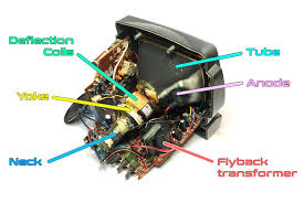
A CRT TV contains:
- Extra High Tension (EHT) voltage, often in the range of 25–30kV, generated by the flyback transformer.
- Large electrolytic capacitors in the SMPS primary section with 300–350V DC across them.
- The picture tube itself, acting as a huge capacitor capable of storing charge even after power is switched OFF.
Safety rules every CRT technician must follow
-
Always discharge the CRT before removing the anode cap.
Use a well-insulated flat screwdriver connected to the chassis ground with a thick wire. Slide the tool under the rubber cap until it touches the metal clip. You may hear a sharp “snap”. Never place your fingers near the metal clip. -
Use the one-hand rule when probing live circuits.
Keep one hand behind your back or in your pocket. This reduces the chance of current passing across your chest and heart in case of accidental contact. -
Use an isolation transformer for live chassis sets.
In some CRT designs, one side of the mains is directly connected to the chassis. Without an isolation transformer, you are effectively connecting the mains to your measuring instruments and your body. -
Wait and measure before touching.
Even after switching off the TV, check the big filter capacitors with a DMM. If necessary, discharge them through a suitable resistor—not by directly shorting with a screwdriver which can damage tracks.
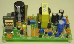
Treat B+ Voltage as the “Health Indicator” of the Whole TV Top 10 Secrets in CRT TV Service in 2025
One of the biggest mistakes in CRT repair is guessing the fault instead of measuring the main supply. Professional technicians always check the B+ voltage very early in their diagnosis.
The B+ line is the main DC rail that feeds the line output section (flyback, HOT, etc.). Typical B+ values are:
- 110–130V DC for 20" to 21" sets.
- 135–150V DC for larger screens or certain flat models.
What happens if B+ is wrong?
-
If B+ is too high:
Picture becomes excessively wide, flyback and HOT run hot, and protection circuits may shut the TV down. Continuous over-voltage often leads to repeated HOT failures. -
If B+ is too low:
Picture width decreases, sometimes the image appears “pulled-in” from left and right. The TV may struggle to start, and the flyback may whistle.
How to check B+ like a pro
- Locate the B+ filter capacitor or the point where the schematic/PCB marks “B+ 115V” or similar.
- Use a DMM set to DC voltage and measure with respect to chassis ground.
- Compare the reading to the expected value. A deviation of more than ±5–10% is suspicious.
If B+ is abnormal, the fault is usually in the SMPS feedback or load:
- Dried primary side capacitors changing feedback behaviour.
- Faulty TL431, optocoupler or reference components.
- Shorted loads in the secondary, pulling the supply down.
Dry Solder Joints – The Silent Reason Behind “Magic” Faults Top 10 Secrets in CRT TV Service in 2025
Many CRT faults look complicated when the real cause is just a cracked solder joint. Heat, mechanical vibration, and age cause solder to develop tiny circular cracks around component pins. This is especially common in high-temperature and high-current areas.
Common dry joint locations
- Flyback transformer pins (large and often stressed).
- Horizontal output transistor (HOT) pins and nearby coils.
- Power resistors in B+ and SMPS sections.
- Vertical IC pins and vertical yoke connector.
- CRT socket pins and RGB amplifier components.
Typical symptoms of dry solder:
- TV works for some time and then suddenly shuts off.
- Picture disappears but tapping the cabinet brings it back temporarily.
- Random colour flicker, lines, or geometric distortion that appears and disappears.
Use a bright inspection lamp and a small magnifier. Look for:
- Dull, grainy or ring-shaped cracks around pins.
- Joints that move slightly when you push the component.
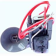
Flyback Transformer – Test It Before You Blame It Top 10 Secrets in CRT TV Service in 2025
In 2025, original flyback transformers for many CRT models are rare and expensive. Some low-quality replacements cause more trouble than the original fault. That is why experts never replace a flyback until they are sure it is at fault.
Symptoms pointing to flyback problems
- No raster or HV even though B+ and HOT are OK.
- Sharp “tik-tik” arcing sound near the flyback area.
- Visible sparking in a dark room around flyback body or focus/screen knobs.
- Focus or brightness suddenly changes if you tap the flyback lightly.
- Set attempts to start but goes into protection, sometimes with a chirping sound.
Before declaring the flyback dead:
- Check the HOT for shorts or leakage and ensure it is mounted with proper insulation and mica.
- Check the damper diode and snubber network around the HOT for shorts or opens.
- Inspect the PCB for carbon tracking under and around the flyback pins.
- If available, use a flyback tester to examine winding condition and insulation.
Vertical Section – Why a Single Horizontal Line Is Usually an Easy Fix Top 10 Secrets in CRT TV Service in 2025
A classic CRT fault is the appearance of a single bright horizontal line across the centre of the screen. The sound is usually normal, and sometimes the TV does not switch off automatically. This is a textbook sign of vertical deflection failure.
Main suspects in vertical collapse
- The vertical IC itself (e.g., LA78040, TDA3654, TDA835x series).
- Electrolytic capacitors in the vertical drive and output section.
- Vertical yoke connections or connector pins.
- Missing supply voltage to vertical IC (for example +12V / +24V line open or low).
A simple professional approach:
- Touch the vertical IC heat sink carefully to check for abnormal heating (power off before touching).
- Measure the supply lines to the IC. If supply is missing, trace back through resistors and diodes.
- Replace all electrolytic capacitors associated with vertical section, especially the pump-up capacitor.
- Inspect the yoke connector and cable for dry joints or broken wires.
CRT Socket & Neck Board – The Real Boss of Color Problems Top 10 Secrets in CRT TV Service in 2025
Many weird colour issues come from the neck board rather than from the tube itself. Customers describe the picture as “fully red”, “too green”, “no blue” or “colours dancing”. In a surprising number of cases, the actual CRT guns are fine.
Typical neck board problems
- Dry solder joints on the CRT socket and RGB output transistors.
- Carbon tracking between closely spaced pins, especially in humid environments.
- Leaky transistors or low-value resistors that have drifted from their original values.
- Loose or corroded socket contacts causing intermittent colour loss.
Professional colour troubleshooting process:
- Remove the neck board and carefully clean it with IPA or a similar circuit cleaner.
- Re-solder all CRT socket pins and components in the RGB amplifier section.
- Compare the cathode voltages for R, G and B; a large difference points to the faulty channel.
- If necessary, temporarily swap components between channels to see if the fault “moves”.
Service Mode & EEPROM – Unlocking the Software Side of CRT TVs Top 10 Secrets in CRT TV Service in 2025
Late-generation CRT TVs have a full microcontroller system with user settings, service options and geometry parameters stored in EEPROM. After replacing the main board or EEPROM, the TV may show strange behaviour until you correct those values.
Common software-related symptoms
- Picture is too wide/narrow even though the hardware is fine.
- Image shifted left/right or top/bottom beyond normal adjustments.
- Hotel mode, child lock or key-lock features stuck ON.
- No colour in AV mode but normal colour in tuner mode, due to wrong option bytes.
Each brand and chassis has its own method to enter service mode, usually a special combination of remote keys and panel buttons. It is worth keeping a small notebook or digital file with service entry sequences for commonly serviced models.
When an EEPROM is badly corrupted:
- Some sets refuse to start or show random characters on screen.
- In many designs, fitting a fresh blank EEPROM allows the microcontroller to auto-program default values.
After EEPROM replacement or auto-initialisation, you will normally need to:
- Adjust vertical size, position and linearity.
- Set horizontal width and centering.
- Correct white balance or colour drive if required.
- Enable or disable options like extra AV inputs, on-screen language, etc.
Degaussing, Purity & Convergence – How Pros Get “Perfect” Picture Top 10 Secrets in CRT TV Service in 2025
Even if the electronic circuits are perfect, a magnetised tube or poorly set yoke can ruin the picture. Customers may complain about colour patches in corners, strange tints on faces or coloured shadows around text.
Degaussing and magnetisation
Each CRT has a degaussing coil and a thermistor (NTC) that briefly powers the coil when the TV is switched on from cold. If the thermistor breaks or the coil is disconnected, magnetisation builds up and colour purity suffers.
- Check that the degaussing coil is plugged in securely.
- Inspect the thermistor for cracks or burning and replace if necessary.
- For strong magnetisation, use a manual degaussing coil and slowly move it around the screen while gradually moving away.
Purity and convergence adjustments
Behind the yoke, you will often find magnet rings and wedges controlling purity and convergence. Unless someone has already disturbed them, you should not adjust these casually. However, if the yoke has been moved or the tube replaced, you may need to re-align them.
A properly degassed tube with correct purity and convergence can deliver a sharp, vibrant image that still looks very good for SD content, even compared to modern flat panels.
Smart Parts Substitution – Surviving Component Shortage in 2025
With CRT production stopped years ago, original spare parts are not always available. Smart substitution is a powerful skill that lets you complete repairs when others give up.
General substitution rules
- Electrolytic capacitors: Voltage rating can always be higher, never lower (e.g. 16V → 25V is OK). Capacitance can be slightly higher in power supply filters (e.g. 1000µF → 1200µF or 1500µF).
- HOT transistors: Use a line output transistor with equal or higher voltage and current ratings, and make sure it is a fast device designed for flyback operation.
- Diodes: In SMPS and horizontal/vertical sections, use fast or ultra-fast diodes, not general-purpose types like 1N4007 unless originally used there.
- Resistors: Power rating must be equal or higher. Never reduce wattage when substituting.
For flybacks, cross-reference guides and online communities (where available) can help identify equivalent models. But always confirm:
- Pin configuration and physical fit.
- Compatibility with B+ voltage and screen size.
- Whether focus and screen controls are included and correctly oriented.
Documentation, Testing & Customer Education – Your Real 2025 Advantage
The final secret is not on the PCB; it is in the way you run your service as a business. Two technicians with the same technical knowledge can earn very different income because one of them is more systematic.
1. Maintain your own repair knowledge base
Use a notebook, spreadsheet or simple app to record every CRT repair you do:
- Brand, model number and chassis code if available.
- Customer complaint (“no power”, “single line”, “no colour”, etc.).
- Measured B+ and other key voltages.
- Actual faulty parts replaced or re-soldered.
- Any special notes (service mode access, EEPROM tricks, etc.).
After some months, you will notice patterns: certain models repeat the same faults. You will start diagnosing them almost instantly, saving time and increasing your daily earning potential.
2. Always load test before delivery
Do not hand over a CRT immediately after it turns on. Run it for at least 30–60 minutes and monitor:
- Temperature of flyback, HOT, vertical IC and SMPS components.
- Stability of geometry and colours after warm-up.
- Behaviour in different modes: tuner, AV, maybe game console input.
3. Educate your customers in simple language
A short, friendly explanation at delivery time can prevent misuse and reduce future faults:
- Ask them not to beat or bang the TV when picture flickers; tell them to call you instead.
- Explain the benefit of a surge protector or stabiliser in areas with unstable mains.
- Advise them not to place large speakers close to the CRT sides to avoid magnetisation.
- Tell them to keep ventilation slots open, not to lock the TV inside a fully closed wooden box.
Customers remember technicians who take time to guide them. This builds strong word-of-mouth, which is still the best advertisement in many local markets.
Essential Tools for CRT TV Service in 2025
You do not need a complete lab to start repairing CRT TVs. With a focused toolkit, you can handle most common faults safely and efficiently.
- Digital multimeter (DMM) with reliable probes and good insulation.
- Isolation transformer for live chassis sets.
- Adjustable soldering station with different tip sizes.
- Desoldering pump or braid for clean component removal.
- High-voltage probe (optional but helpful for advanced work).
- Flyback tester (if budget permits) to quickly judge transformer health.
- Manual degaussing coil for stubborn purity issues.
- Magnifier lamp for spotting dry joints and cracks.
- Insulation tape, heat shrink and cable ties for neat, safe finishing.
FAQ – CRT TV Service in 2025
Is CRT TV servicing still profitable in 2025?
Yes, in many locations it is still profitable because there are fewer technicians who know CRT in depth, while many sets are still in use for cable TV, local channels, gaming and DVD playback. You can position yourself as a niche specialist and charge reasonable, sustainable rates.
What is the most important thing to learn first?
The most important foundation is safe working practices and a clear understanding of the power supply/B+ section. Once you are comfortable with SMPS operation and B+ regulation, other sections (vertical, horizontal, colour, microcontroller) become much easier to understand and repair.
Should I invest time learning service modes and EEPROM tricks?
Definitely yes. Modern CRTs rely heavily on software parameters for geometry and options. Being able to quickly reset, initialise or tune these values will save you time and can rescue TVs that other technicians may declare “unrepairable”.
Can I learn CRT service if I only have mobile repair background?
Yes, many mobile technicians successfully learn CRT servicing. The main difference is the presence of high voltage and bigger magnetic components. If you respect the safety rules and practise systematic troubleshooting, your existing soldering and diagnosis skills are already a strong base.
Final Thoughts – Becoming the “Go-To” CRT Specialist in Your Area
CRT technology might be old, but the demand for honest, skilled technicians is very current. When you combine safety, measurement-based diagnosis, smart parts handling and good customer communication, you naturally move into the top tier of CRT service professionals.
If you treat each TV as a learning opportunity and carefully note your findings, your experience compounds. Within months, you will recognise common patterns at a glance. Within a few years, you become the person other technicians call when they are stuck.
Use these top 10 secrets as a checklist for every CRT that lands on your table:
- Respect and manage high voltage safely.
- Check and stabilise B+ before anything else.
- Re-solder suspect joints to eliminate intermittent faults.
- Test flybacks logically instead of guessing.
- Handle vertical, colour and purity faults with structured methods.
- Leverage service mode and EEPROM knowledge.
- Apply smart, reliable component substitutions.
- Document, test and educate customers to build long-term trust.
Step by step, these habits will build your confidence, your skills and your income as a CRT TV technician in 2025 and beyond.
Top 10 Secrets in CRT TV Service in 2025
Top 10 Secrets in CRT TV Service in 2025 (Professional Technician Guide) CRT TV Service…
Ultimate CRT TV Microcontroller and EEPROM Repair Guide – Fix Like a Pro
Ultimate CRT TV Microcontroller and EEPROM Repair Guide – Fix Like a Pro! Introduction CRT…
How to Replace Faulty Capacitors in CRT TVs.
How to Replace Faulty Capacitors in CRT TVs. Introduction Faulty Capacitors in CRT TVs, though…
Fix Low or Distorted Audio in CRT TVs – Ultimate Troubleshooting Guide
Fix Low or Distorted Audio in CRT TVs – Ultimate Troubleshooting Guide Introduction Having trouble…
CRT TV No Sound? Here’s the Repair Solution
CRT TV No Sound? Here’s the Repair Solution Introduction : A common issue with CRT…
CRT TV Screen Shrinking and Expanding – How to Fix
CRT TV Screen Shrinking and Expanding – How to Fix IntrIntroduction Is your CRT TV…
CRT TV Distorted Picture? Ultimate Troubleshooting Guide for Quick Fixes!
CRT TV Distorted Picture? Ultimate Troubleshooting Guide for Quick Fixes! CRT TV Distorted Picture? Ultimate…

CRT TV Color Issues: Fixing Red, Green, Blue Problems
CRT TV Color Issues: Fixing Red, Green, Blue Problems CRT TV Color Issues: Fixing Red,…
![7-Step Guide to Fix CRT TV No Display or Black Screen [Solve Now]](https://tamiltechnicians.com/wp-content/uploads/2025/03/crt-tv-no-display.jpg)
How to Fix CRT TV No Display or Black Screen Issues
How to Fix CRT TV No Display or Black Screen Issues. Introduction CRT TVs are…
Complete Guide to CRT TV Fault Diagnosis and Repair
Complete Guide to CRT TV Fault Diagnosis and Repair. Introduction CRT TVs, though older technology,…
CRT TV Vertical Deflection Problems & Fixes
CRT TV Vertical Deflection Problems & Fixes introduction : CRT TV Vertical Deflection Problems &…
Common CRT TV Power Supply Issues and How to Fix Them
Common CRT TV Power Supply Issues and How to Fix Them Introduction CRT TVs, although…
Troubleshooting Horizontal Deflection Issues
🛠️ Troubleshooting Horizontal Deflection Issues 📌 Introduction Horizontal deflection issues in CRT TVs and monitors…
How to Test a CRT TV Flyback Transformer
🛠️ How to Test a CRT TV Flyback Transformer – Step-by-Step Guide 🔹 Introduction Test…
CRT TV Power Supply Issues: Troubleshooting & Fixes
CRT TV Power Supply Issues: Troubleshooting & Fixes 🔹 Introduction CRT TV Power Supply Issues…
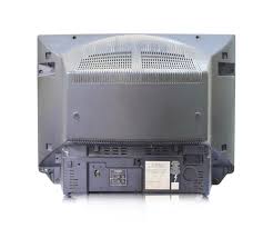
How to Open a CRT TV Back Cover Safely in 5 Easy Steps
🛠️ How to Open a CRT TV Back Cover Safely – Step-by-Step Guide Want to…
Recommended CRT TV Service Tools (Amazon)
These tools are highly useful for safe and professional CRT TV servicing. (External links – opens in a new tab)
Essential Multimeter for CRT TV Diagnostics
A reliable digital multimeter is the first tool you need for checking B+ voltage, heater lines, power supply rails and basic continuity in CRT TVs.
Soldering Station for Professional Repairs
A temperature-controlled soldering station helps you re-solder dry joints, replace capacitors and ICs cleanly without damaging PCB tracks on CRT boards.
External link :
CRT TV PCB BUY LINK CLICK HERE>>>>
Super Series 4K Ultra HD Smart QLED Google TV AR55QDXGU2875AT