How to Assemble a 5.1 Amplifier Easily – Complete 2025 Guide
Want to build your own 5.1 home theater amplifier at home or in your small workshop? In this Tamil Technicians guide we will see what components you really need, how to wire everything safely, how to choose the correct speakers and ohms, and how to remove hum and noise like a pro.
Many technicians and hobbyists love to assemble an amplifier, but get confused when it comes to 5.1 systems – there are more channels, more wires and more chances for humming sound. In this article we are going to break everything into simple blocks, just like separate cards on your workbench, so you can follow and build step by step.
Note: In this first version the content is in English only, but written with Tamil technicians in mind. You can easily add a Tamil translation block later and connect it to the language toggle at the top using a small JavaScript snippet.
Block 1: Components Required for a 5.1 Amplifier
1.1 Main Amplifier Boards
First decide whether you are going to assemble from individual ICs or use ready-made kit PCBs. For most beginners and even busy technicians, kit-based PCBs are faster and more reliable.
- 5 x satellite channels – usually 10 W to 40 W per channel.
- 1 x subwoofer channel – 50 W to 200 W depending on room size.
- Each board will have its own power supply requirement (single or dual rail).
Popular choices are TDA series, STK modules, or modern Class-D boards which are compact and generate less heat.
1.2 Pre-Amplifier & Decoder Section
For a true 5.1 experience you need a pre-amplifier / decoder board that takes stereo or digital input and splits it into front left/right, rear left/right, center and subwoofer (LFE).
- 5.1 decoder / pre-amp PCB with volume, balance and sub level controls.
- Input selector (AUX, Bluetooth, TV, DVD etc.).
- Remote volume / standby support if required.
Many online boards use ICs like PT2323, PT2322, LM1036 or dedicated surround ICs.
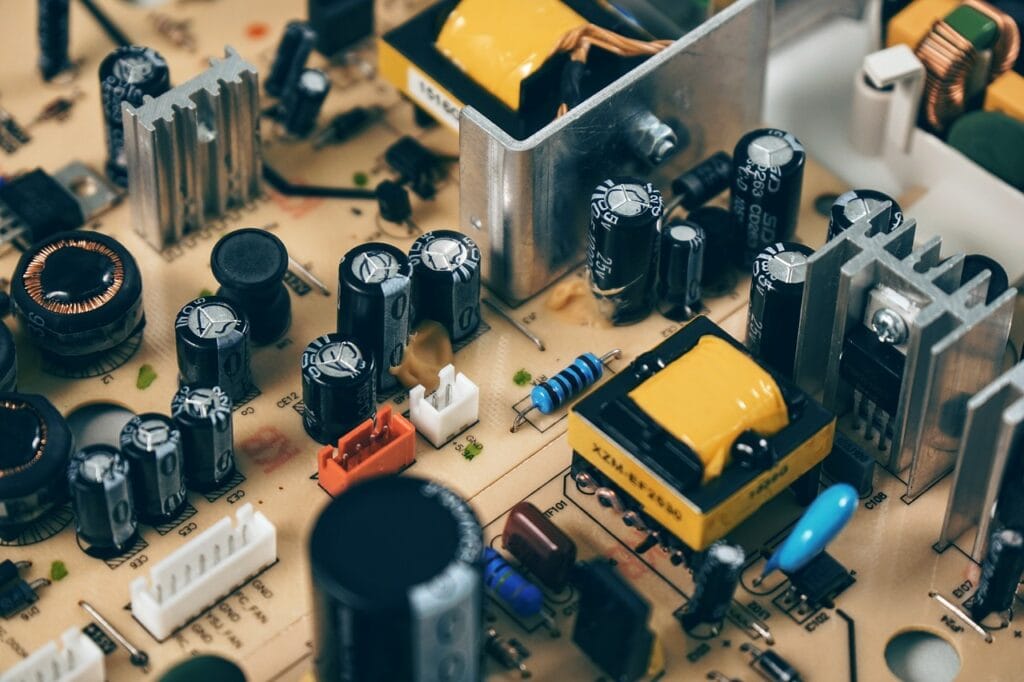
1.3 Power Supply Components
The power supply is the heart of any amplifier. A weak or noisy supply will introduce hum, distortion and even damage ICs.
- Step-down transformer (primary and secondary ratings discussed in Block 3).
- Bridge rectifier (or four high-current diodes).
- Filter capacitors – typically 4 700 µF to 10 000 µF and above, 35–63 V.
- Voltage regulators for pre-amp section (7812 / 7805 etc.).
- NTC inrush limiter / soft start circuit for big toroidal transformers.
Keep the power supply on a separate PCB or metal corner to reduce noise.
1.4 Protection & Control Parts
To make your 5.1 amplifier behave like a commercial home theater, add these small but important control and protection items:
- Speaker protection relay board (delay + DC detection).
- Over-temperature sensor for big heatsinks.
- Soft-start / mute control from the pre-amp.
- Fuse holders – separate fuses for primary and secondary if possible.
- Front panel power switch & LED indicators.
Never run a powerful subwoofer channel directly without fuse or protection. A wrong wiring or failed IC can send DC to the speaker and burn the voice coil.
1.5 Mechanical & Miscellaneous Items
Apart from electronics, mechanical parts decide the final look and safety.
- Metal or strong wooden cabinet with proper ventilation slots.
- Big aluminum heatsink for power ICs or transistors.
- Insulation mica / pads, thermal paste and mounting screws.
- Input / output connectors (RCA, banana, spring-type speaker terminals).
- Good quality shielded audio cable for signal sections.
- Heat-shrink tubes, cable ties and labels for clean wiring.
Block 2: Understanding the 5.1 Amplifier Layout
2.1 Simple Block Diagram in Words
Imagine your 5.1 amplifier as a series of blocks arranged from left to right:
- Input sources (TV, mobile, DVD, Bluetooth receiver).
- Pre-amp / decoder board (volume and tone control).
- Individual power amplifier boards (5 small + 1 subwoofer).
- Speaker protection and output connectors.
- Master power supply feeding all these blocks.
Wiring becomes easier when you follow this flow mentally and physically in the cabinet.
2.2 Channel Power Distribution
Most home theater rooms do not need equal power on all channels. A common and practical choice is:
- Front L/R: 30–60 W per channel (main music and effects).
- Center: 30–60 W (dialogue clarity).
- Rear L/R: 20–40 W (surround ambience).
- Subwoofer: 80–200 W (low-frequency impact).
You can combine some channels in a single multi-channel IC or use separate mono boards depending on availability.
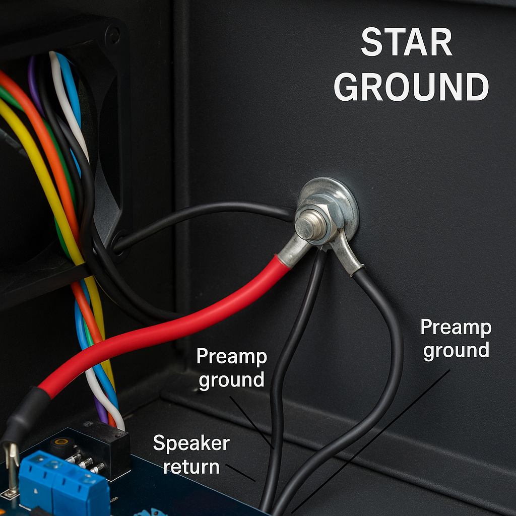
2.3 Grounding Philosophy
A big mistake in 5.1 builds is random ground wiring. To reduce hum, follow the star grounding method:
- Pick one strong ground point near the filter capacitors as the star point.
- Bring separate ground wires from each amplifier board to this star point.
- Bring pre-amp ground separately to the same star, not piggybacked on power lines.
- Connect chassis (body) to earth pin of mains through a safety resistor / capacitor if needed.
This simple star ground design alone can remove a lot of humming problems.
Block 3: Primary & Secondary Voltage – Choosing the Right Transformer
3.1 Understanding Primary Voltage
Primary is the input side of the transformer which connects to your mains (AC supply). In India, we commonly have 230 V AC, 50 Hz. So you will see transformer ratings like:
- 230 V / 12–0–12 V, 5 A
- 230 V / 24–0–24 V, 8 A
- 230 V / 0–24 V, 10 A (single secondary)
Always use proper mains wire, switch and fuse on the primary side. Never touch or troubleshoot the primary connections while power is ON.
3.2 Calculating Secondary Voltage for Satellite Channels
Most low-to-medium power IC amplifiers work well in the ±18 V to ±35 V DC range. To get this DC, we use AC secondary from transformer and rectify it.
A quick thumb rule:
- DC after bridge rectifier ≈ AC secondary × 1.41 (minus some loss).
Example:
- If you use 18–0–18 V transformer, DC will be around ±24 V.
- This is good for 30–40 W per channel in many Class-AB ICs.
For 5 satellite channels of 30 W each, a 18–0–18 V, 8–10 A transformer is practical.
3.3 Secondary Voltage for Subwoofer Channel
The subwoofer needs more power and sometimes a separate transformer:
- For 100 W Class-AB sub: 24–0–24 V, 6–8 A transformer is common.
- For Class-D boards, the requirement might be 35 V single supply or similar.
Always read the recommended voltage on the PCB silkscreen or datasheet. Do not exceed it just to get “more power”; the IC will only run hotter and fail.
3.4 Separate vs Shared Transformers
You have two options:
- Single big transformer: Simpler wiring, but more load and possible hum.
- Two transformers: One for satellites, one for subwoofer – cleaner sound.
In many DIY designs, using a separate transformer for subwoofer gives better bass control and keeps noise away from front channels.
3.5 Safety with High Voltage Capacitors
Filter capacitors store charge even after power is switched off. Always discharge them safely before touching the board.
- Use a 10 kΩ 5 W resistor with insulated leads.
- Hold with insulated clip and connect across capacitor terminals for few seconds.
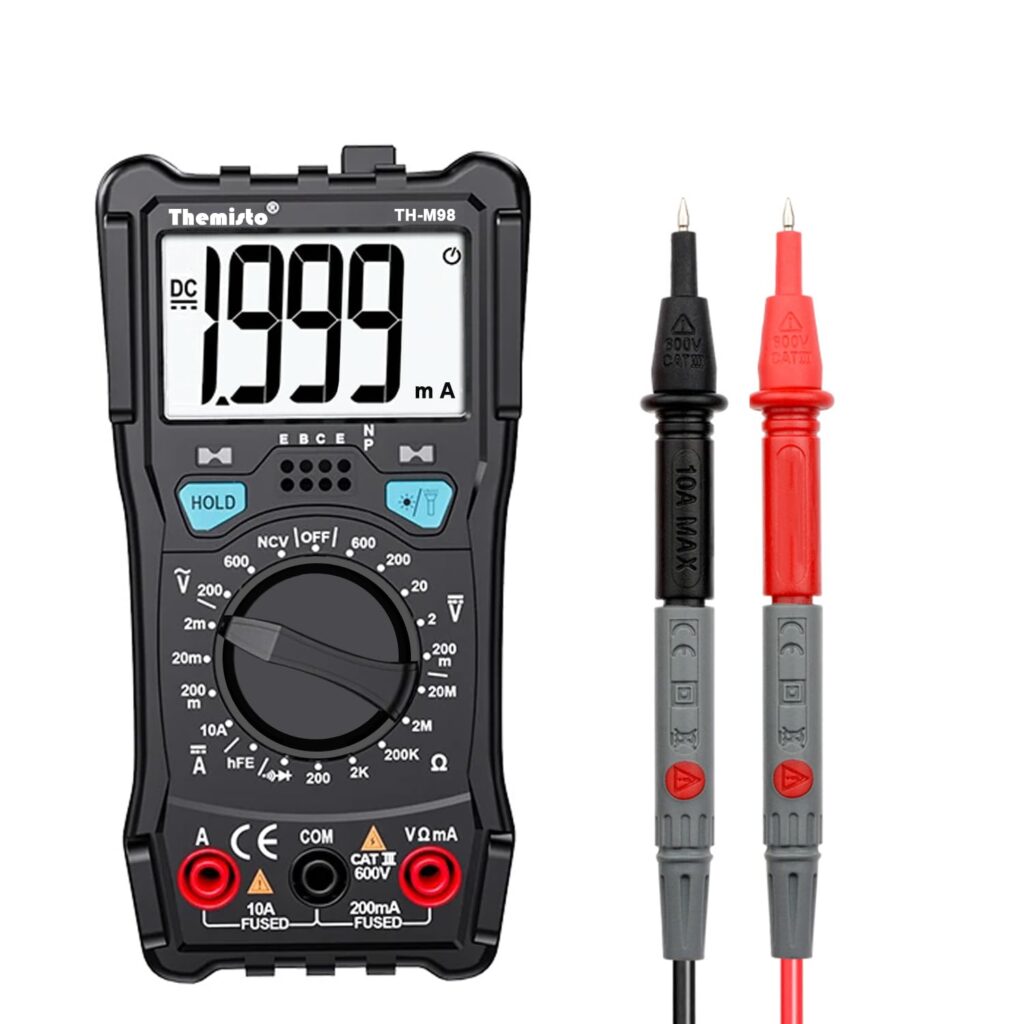
- Verify with multimeter that voltage is near zero.
Do not discharge capacitors directly with a screwdriver tip. It can damage the capacitor and create dangerous sparks.
Block 4: Wiring the 5.1 Amplifier Step by Step
4.1 Plan Your Layout on Paper
Before soldering or drilling, draw a top-view of your cabinet on paper:
- Left side – transformer and power supply board.
- Center – amplifier boards with heatsink.
- Right side – pre-amp board, input connectors and volume knobs.
- Backside – speaker terminals and mains inlet.
Keep high-voltage AC wires twisted and away from small signal lines.
4.2 Power Wiring
From the transformer secondary, go to the bridge rectifier and filter capacitors. From there, take thick gauge wires (+V, GND, –V) to each amplifier board.
- Use separate supply wires for left and right side boards if possible.
- Twist +V and –V together with corresponding ground to reduce loop area.
- Route power wires along the cabinet edges, not across the pre-amp area.
4.3 Signal Wiring from Pre-amp to Power Amp
For each of the 6 channels, you need one shielded cable:
- Inner conductor – audio signal.
- Outer braid – ground, connected at both ends to the local ground points.
Keep these cables as short as practical and never bundle them with AC mains wires.
4.4 Speaker Output Wiring
From each amplifier PCB, take two wires (positive and negative output) to the respective speaker terminal on the back panel.
- Use thicker wire for subwoofer output (2.5 mm² or similar).
- Label each terminal clearly: FL, FR, RL, RR, C, SW.
- If using protection relay board, route output through the relay contacts.
Secure wires with cable ties so they do not shake and break when the cabinet is moved.
4.5 Earthing & Hum Reduction Wiring
Connect the mains earth (green wire) firmly to the metal cabinet. If your amplifier uses a two-pin plug only, you can still connect signal ground to chassis via a resistor-capacitor network (for example 10 Ω + 100 nF in parallel).
This gives a reference path for noise without creating ground loops.
Block 5: Choosing Speakers & Ohms Calculation
5.1 Basic Ohms and Power Matching
Every amplifier board will specify an output power rating at a particular load, for example: 50 W @ 8 Ω or 80 W @ 4 Ω.
To avoid damage:
- Never use a speaker with lower impedance than specified (e.g., 2 Ω on a 4 Ω minimum amp).
- You can safely use higher impedance speaker (8 Ω on a 4 Ω amp) – output power will be a bit less.
5.2 Series and Parallel Ohms
Sometimes you may want to combine two speakers on one channel. Use simple formulas:
- Series connection: Rtotal = R₁ + R₂
- Parallel connection: 1/Rtotal = 1/R₁ + 1/R₂
Example:
- Two 4 Ω speakers in series → 8 Ω total.
- Two 8 Ω speakers in parallel → 4 Ω total.
For home 5.1 systems, it is usually better to keep one speaker per channel, not multiple speaker combinations.
5.3 Recommended Speaker Ratings for 5.1 System
For a balanced system in a medium sized hall or living room:
- Front L/R: 6.5″ or 8″ speakers, 60–100 W, 8 Ω.
- Center: Horizontal center speaker with dual 4″ or 5.25″ drivers, 60 W, 8 Ω.
- Rear L/R: Compact 4″ or 5.25″ speakers, 30–60 W, 8 Ω.
- Subwoofer: 10″ or 12″ woofer, 150–250 W, 4 Ω or 8 Ω depending on amp.
Always check the continuous (RMS) rating rather than only music / PMPO values.
5.4 Crossover & Subwoofer Enclosure
For the subwoofer, use either:
- Active crossover on the sub amp PCB (built-in low-pass filter).
- Or passive crossover network inside the box (inductor + capacitor).
Choose a proper enclosure (sealed or ported) according to woofer parameters. A badly designed box can make even an expensive woofer sound weak.
5.5 Matching Speaker Sensitivity
Each speaker has a sensitivity rating (for example 88 dB @ 1 W/1 m). Try to keep front and center speakers with similar sensitivity so dialogues are natural.
If one speaker is too loud compared to others, you can trim its level in the pre-amp or use a small padding resistor network.
Block 6: Noise, Hum & Distortion – How to Solve
6.1 Types of Unwanted Sounds
In a 5.1 amplifier you may face different noise issues:
- 50 Hz or 100 Hz hum: deep buzzing from power supply / ground loop.
- Hissing noise: high-frequency noise from pre-amp or bad grounding.
- Click / pop: when switching ON/OFF or changing inputs.
- Distortion / clipping: harsh sound at high volume due to insufficient power.
6.2 Check Power Supply First
Most hum problems come from the power supply. Do these checks:
- Verify transformer secondary voltage is within spec under load.
- Confirm filter capacitors are of correct value and not dried out.
- Check rectifier diodes for heating or abnormal drop.
- Keep transformer physically away from pre-amp and input cables.
6.3 Ground Loop & Wiring Fixes
If hum appears only when certain external equipment is connected (like TV or PC), it might be a ground loop.
- Use ground-loop isolator transformer on the affected input line.
- Ensure all devices are connected to the same power outlet strip.
- Double-check star grounding inside the amplifier cabinet.
6.4 Reducing Hiss & HF Noise
High frequency hiss usually comes from:
- High gain in pre-amp stages.
- Poor quality op-amps or wrong component values.
- Long unshielded signal cables.
Reduce overall gain, use low-noise op-amps, and keep signal cables shielded and short.
6.5 Switch-On Pop & Protection
To avoid loud pops when you switch on:
- Use speaker protection relay with delay (2–3 seconds).
- Ensure pre-amp comes up to stable DC level before power amps are enabled.
- Use muting pin of the amplifier IC if available.
This protects both your ears and your speakers.
Block 7: Safety Tips While Assembling & Testing
7.1 Workbench Safety
Treat your workbench like a mini-laboratory:
- Use an isolation transformer if you regularly work with mains powered devices.
- Keep one hand in your pocket when probing live circuits to avoid current path through heart.
- Wear slippers / shoes and avoid working on wet floor.
- Keep a fire extinguisher and first-aid kit nearby.
7.2 Heat Management
Power amplifier ICs can get very hot at full volume. Use:
- Thick aluminum heatsink with fins facing vertical direction.
- Good quality thermal paste between IC and heatsink.
- Optional 12 V fan, powered from a small regulator, blowing across fins.
Do not enclose the amplifier in a fully sealed box; always provide air vents.
7.3 Fuse & Over-current Protection
On the primary side, use a slow-blow fuse matching transformer rating. On the secondary side you can add quick-blow fuses or resettable polyswitches for extra safety.
Never bypass a fuse with wire; it is there to protect you and your equipment.
7.4 Speaker Safety During Testing
During first power-up, do not connect your expensive speaker set immediately.
- Use a dummy load resistor (8 Ω, 50 W) or an old test speaker.
- Check for DC voltage at output. It should be close to zero (few tens of mV).
- Slowly increase volume while monitoring sound and heat.
7.5 Handling Primary & Secondary Voltages Safely
Even secondary voltages (like 24–0–24 V) can give strong shock when combined with mains earth. Treat them with respect.
- Keep all bare mains and secondary terminals covered with heat-shrink or sleeves.
- Use proper grommets where wires pass through metal panels.
- Label all high-voltage areas clearly inside the cabinet.
Final Checklist – From Loose Boards to a Working 5.1 Amplifier
If you followed all the blocks above, you now know much more than simply “connect red wire here and black wire there”. You understand what components are required, how to choose primary and secondary voltages, how to calculate speaker ohms, and how to keep noise under control.
Before you close the cabinet, run through this quick checklist:
- All boards firmly screwed and spaced from metal using stand-offs.
- Star grounding point fixed and all grounds properly connected.
- Transformer wiring double-checked – primary, secondary, fuse and switch.
- No loose strands or exposed wires touching cabinet body.
- Speaker terminals correctly labelled and tightened.
- Ventilation holes sufficient and fan (if used) blowing freely.
buy amplifier item’s :
5.1 amplifier complete set. click here >>>>>
5.1 pro logic board buy click here >>>>>>>>
Related more posts :
How to Assemble a 5.1 Amplifier Easily – Complete 2025 Guide
How to Assemble a 5.1 Amplifier Easily (2025 Full Guide) | Tamil Technicians English How…
Ultimate Guide to Power Supply for Electronics Repair & Projects
Ultimate Guide to Power Supply for Electronics Repair & Projects | Tamil Technicians Ultimate Guide…

Online Electronics Repair Training in Tamil | TAMIL TECHNICIANS
Online Electronics Repair Training in Tamil | [TAMIL TECHNICIANS] Online Electronics Repair Training in Tamil…
iPhone 17 Series – Complete Guide (Features, Price in India, Specs)
iPhone 17 Series – Complete Guide (Features, Price in India, Specs) | Tamil Technicians Home…
iPhone 17 Series – முழுமையான வழிகாட்டி (Features, Price in India, Specs)
iPhone 17 Series – முழுமையான வழிகாட்டி (Features, Price in India, Specs) | Tamil Technicians Home…
Kill Audio Hum: A Practical Guide to Star Ground & Chassis Ground
Kill Audio Hum: A Practical Guide to Star Ground & Chassis Ground TamilTechnicians • Audio…

Edge AI: Cloud இல்லாமல் Mobile & IoT Devices‑ல் Real‑Time Intelligence (2025)
Edge AI: Cloud இல்லாமல் Mobile & IoT Devices‑ல் Real‑Time Intelligence Edge AI 2025 Guide Edge…

Smartphone Dead Issue? Full Board-Level Repair Steps
Smartphone Dead Issue? Full Board-Level Repair Steps 📱 Smartphone Dead Issue? Full Board-Level Repair Steps…
Top 5 Multimeters Under ₹1000 for Beginners in India (2025) – Expert Guide
Top 5 Multimeters Under ₹1000 for Beginners (2025 Guide) Top 5 Multimeters Under ₹1000 (2025…
7 Reasons Your Amplifier Overheats & Easy Fixes to Stop It (2025).
Why is My Amplifier Overheating? Causes and Fixes. Introduction : Amplifier Overheating When an amplifier…
How to Fix Distorted Sound in an Audio Amplifier (Ultimate Guide).
How to Fix Distorted Sound in an Audio Amplifier (Ultimate Guide) How to Fix Distorted…
How Audio Amplifiers Work: A Simple Guide for Beginners.
How Audio Amplifiers Work: A Simple Guide for Beginners. Introduction Have you ever wondered how…
What is an Audio Amplifier? The Ultimate Beginner’s Guide to Sound Technology.
What is an Audio Amplifier? The Ultimate Beginner’s Guide to Powerful Sound Technology What is…
Audio Amplifier Service Training – Repair Guide & Troubleshooting Tips
Audio Amplifier Repair Training – Repair Guide & Troubleshooting Tips Common Audio Amplifier Problems and…