Kill Audio Hum: A Practical Guide to Star Ground & Chassis Ground
If your DIY amplifier or mixer hisses, hums, or buzzes, the root cause is often grounding and layout. This guide shows a clean, repeatable way to wire star ground and bond the chassis, separate noisy and sensitive wiring, apply shielded links and local decoupling, and verify the fix with simple tests.
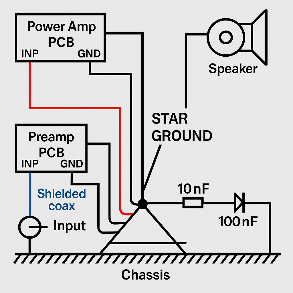
What is Star Ground (and Why)?
Bring every return (power, preamp, speaker return) to a single 0V star point via separate wires. This prevents ground loops and slashes hum.
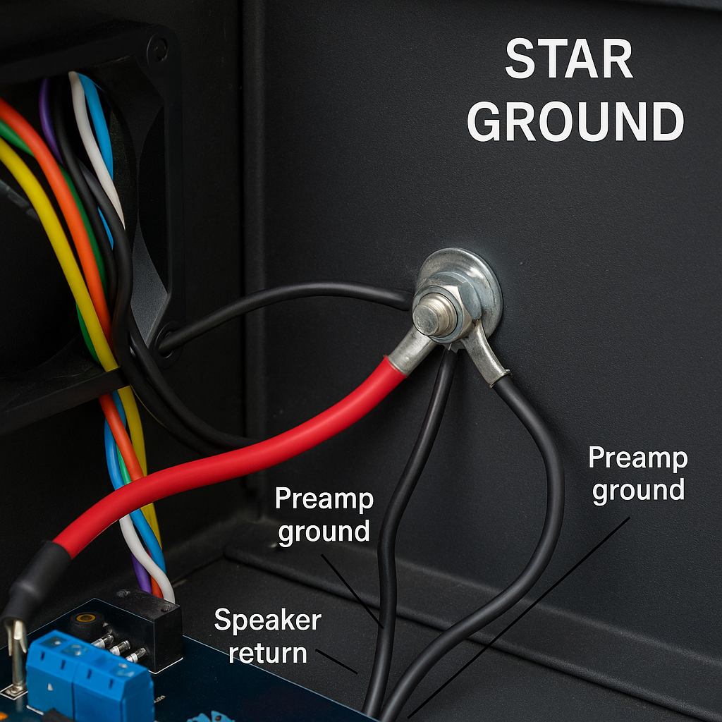
Chassis Bond — Real View
Use a bolt with star washer and ring terminals on the metal chassis. Preamp ground, power ground, and speaker return land here (via the star). Safety earth stays bolted directly to the chassis.
Separate AC Power and Signal Paths
Keep mains/transformer/fan wiring on one side; inputs and other low-level signal on the opposite side. If they must cross, cross at 90°, never run in parallel.
Twisted Pairs & Short Runs
Twist AC secondaries, speaker +/return, and other high-current pairs. Keep signal wires short and tidy. This alone can halve audible hum.
Use Shielded Coax for Low-Level Links
Between RCA→Preamp and Preamp→Power amp, use RG174 or mic-grade cable. Tie the shield at a single end (source or star) to avoid loops.
Ground-Loop Breaker Network
Between star 0V and chassis: 10 Ω resistor in parallel with 100 nF capacitor, plus anti-parallel diodes. It keeps safety continuity while quashing loop currents.
Decoupling & Snubbers
At each amp/op-amp supply pin: 100 nF ceramic + 10–47 µF electrolytic. Use RC snubbers at the rectifier/secondaries to tame buzz from switching edges.
Quick Test Checklist
1) Input shorted → nearly silent. 2) Bypass preamp to isolate sources. 3) Rail ripple < 50–100 mV AC. 4) Add long cables; hum must stay gone.