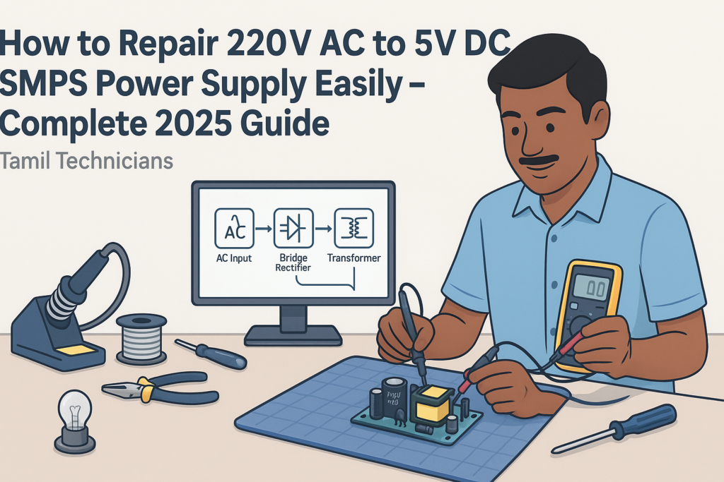
How to Repair 220V AC to 5V DC SMPS Power Supply Easily – Complete 2025 Guide
In this detailed guide, you will learn how a 220V AC to 5V DC SMPS power supply works and how to repair it step by step. We will cover safety rules, internal blocks, every important component, and a practical troubleshooting flow used by professional technicians.
Table of Contents
- 1. Introduction: What Is a 220V AC to 5V DC SMPS?
- 2. Safety First: High Voltage Precautions
- 3. Tools and Basic Skills You Need
- 4. Inside a 5V SMPS: Block Diagram Overview
- 5. Important SMPS Components Deeply Explained
- 6. How to Identify Sections on the SMPS PCB
- 7. Common Problems in 220V to 5V SMPS (Symptoms)
- 8. Step-by-Step SMPS Repair Procedure
- 9. Selecting and Replacing SMPS Components
- 10. Testing, Reassembly, and Burn-In
- 11. Pro Tips to Reduce Noise, Heat, and Future Failures
- 12. FAQ – Frequently Asked Questions
Introduction: What Is a 220V AC to 5V DC SMPS?
Today almost every mobile charger, router adapter, LED strip driver, and small electronics gadget uses a 220V AC to 5V DC SMPS (Switched Mode Power Supply). Instead of a heavy transformer, it uses high-frequency switching to convert mains 220V AC into a stable 5V DC output.220V AC to 5V DC SMPS repair
Because these adapters are cheap and compact, they fail often. Most people simply throw them away and buy a new one. But if you know how SMPS works and how to diagnose it safely, you can repair many units within a few minutes and save money – or even start a small side business doing adapter repairs.
In this 2025 updated guide, we will:
- Understand how a 220V to 5V SMPS works internally
- Learn the function of every key component on the board
- Follow a professional step-by-step repair method
- See how to select replacement parts correctly
- Learn how to test the SMPS safely with and without load
Safety First: High Voltage Precautions
A 220V AC input SMPS is not a low-voltage toy. The primary side is directly connected to mains. Wrong handling can cause electric shock or serious injury. Always respect high voltage.
2.1 Basic Safety Rules
- Always unplug the SMPS from the mains before opening the case.
- Wait and discharge big capacitors before touching the board.
- Use one hand only when probing powered circuits; keep the other away from live parts.
- Use an isolation transformer for safe live testing if available.
- Never work on live mains electronics if you are tired or distracted.
- Keep metal jewelry (rings, chains, watch) away from the workbench.
2.2 Discharging the Bulk Capacitor Safely
On the primary side, after the bridge rectifier you will find a big electrolytic capacitor, typically 400V, 4.7–100 µF. It can hold more than 300V DC even after unplugging from the mains.
- Step 1: Confirm the adapter is unplugged from AC.
- Step 2: Use a multimeter in DC voltage mode and measure across the capacitor terminals.
- Step 3: If voltage is above ~30V, discharge it through a high-value resistor (e.g., 100kΩ–220kΩ, 1–2W) for a few seconds.
- Step 4: Re-check with the multimeter; voltage should drop below 5V.
Never short the capacitor directly with a screwdriver. It can cause sparks, damage pads, or shock.
Tools and Basic Skills You Need
To repair 220V AC to 5V DC SMPS units easily and consistently, you need a small set of tools and some basic skills.
3.1 Essential Tools
- Digital Multimeter (DMM) – for voltage, resistance, and continuity checks.
- 60W Soldering Iron – with a fine tip for through-hole components.
- Solder Wire (60/40 or lead-free) and flux.
- Desoldering pump or desoldering braid.
- Insulated screwdriver set – for opening cases and light prying.
- Series test lamp (optional but highly recommended) – 60–100W bulb in series with mains to limit current during live tests.
- Magnifying glass – to find hairline cracks and tiny burn marks.
3.2 Helpful Extra Tools
- Hot air station – for SMD ICs and compact boards.
- ESR meter – for checking electrolytic capacitors quality.
- Isolation transformer – for safe high-voltage live testing.
- Bench power supply – to test 5V circuits independent of mains.
3.3 Basic Skills Required
- Reading resistor color codes and capacitor markings.
- Using a multimeter in continuity, resistance, and DC voltage modes.
- Soldering and desoldering components without damaging pads.
- Basic understanding of diode direction and MOSFET pinouts.
Inside a 5V SMPS: Block Diagram Overview
Almost all 220V AC to 5V DC SMPS adapters follow the same basic structure. The IC part numbers may change, but the blocks remain similar.
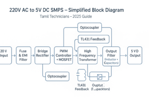
4.1 Main Blocks in a Typical SMPS
- EMI Filter & Fuse – protects against surges and noise from mains.
- Bridge Rectifier – converts AC to DC.
- Bulk Capacitor (High-Voltage) – smooths the rectified DC (around 300V DC).
- PWM Controller IC + MOSFET – chops high-voltage DC at high frequency.
- High-Frequency Transformer – isolates and steps down voltage.
- Secondary Rectifier Diode(s) – converts high-frequency AC back to DC.
- Output Filter (Inductor + Capacitors) – smooths to clean 5V DC.
- Feedback Circuit – optocoupler + reference IC (TL431 etc.) keep 5V regulated.
Whether you open a phone charger or a router SMPS, you will see these blocks in some form. Learning to recognize them visually is the first step towards easy repair.
Important SMPS Components Deeply Explained
In this section, we will go a bit deeper into the major components you will see on a 220V to 5V SMPS board. Understanding what they do helps you to decide which part is likely faulty.
5.1 Fuse and NTC Thermistor
At the very input, you will usually see a small fuse and sometimes a green or black disc-shaped component called an NTC thermistor.
- Fuse – A small safety device that opens (blows) when current exceeds a safe limit. If blown, there is usually a short circuit further inside.
- NTC Thermistor – Limits inrush current when you first plug in the adapter. Its resistance drops as it warms up.
5.2 EMI Filter and MOV
For better quality SMPS, you will find:
- Common-mode choke – A small transformer-like coil that blocks noise.
- X and Y capacitors – Special safety capacitors for filtering differential and common-mode noise.
- MOV (Metal Oxide Varistor) – Protects against high voltage surges; it clamps overvoltage spikes.
Cheaper chargers may skip some of these parts to reduce cost, but the basic operation remains the same.
5.3 Bridge Rectifier and High-Voltage Capacitor
The AC mains is then fed into a bridge rectifier. This may be:
- A single black block marked something like MB6S, DB107, etc.
- Or four separate diodes (often 1N4007 or similar) arranged as a bridge.
The rectified DC is around 310V DC (for 220–240V mains) and is smoothed by a big capacitor typically written like: 400V 4.7µF, 400V 10µF, or 400V 22µF.
5.4 PWM Controller IC and Power Switch (MOSFET)
This is the heart of the SMPS. There are common types:
- Separate PWM IC + MOSFET – e.g., IC UC3842/3843 with an external MOSFET.
- Integrated switcher IC – e.g., TNY series, VIPer series, etc., where the MOSFET is built-in.
The PWM IC switches the MOSFET on and off rapidly (tens of kHz). Each pulse transfers energy through the transformer. The duty cycle (ON time) is adjusted according to the feedback from the output.
5.5 High-Frequency Transformer
The transformer is typically a yellow or black block with ferrite core. It performs:
- Galvanic isolation – separates dangerous primary from safe secondary.
- Voltage conversion – high-voltage primary to low-voltage secondary (5V).
- Energy transfer at high frequency – smaller size compared to 50Hz iron transformer.
Faults in the transformer itself are rarer, but badly burned units or visible cracks may require replacement.
5.6 Secondary Rectifier Diodes
On the low-voltage side, the high-frequency AC from transformer is rectified using fast recovery or Schottky diodes. For 5V output, you may see parts like:
- SS14, SS24, SR560, etc.
- Larger adapters may use dual-diode packages like MBR20100 etc.
If these diodes short, the SMPS may blow the fuse or shut down immediately.
5.7 Output Filter: Inductor and Capacitors
After rectification, the 5V DC is filtered by a small inductor and electrolytic capacitors, e.g.: 6.3V 470µF, 10V 1000µF.
- Bad capacitors (high ESR) cause ripple, noise, and low voltage under load.
- You may see bulging tops or leaked electrolyte in failed caps.
5.8 Feedback Circuit: Optocoupler and TL431
To keep the 5V stable, the output is monitored by a feedback circuit:
- TL431 (or equivalent) – a programmable reference IC. It compares output voltage to an internal 2.5V reference.
- Optocoupler – transfers the error signal across the isolation barrier to the primary PWM IC.
A change in output voltage causes change in optocoupler current, which adjusts the PWM duty cycle and brings 5V back into regulation.
5.9 Snubber Network and Startup Resistor
Two more important elements:
- Snubber network – typically a resistor-capacitor (RC) combination or RCD network across primary winding or MOSFET. It absorbs voltage spikes and protects the MOSFET.
- Startup resistor – a high-value resistor that provides initial power from high-voltage DC to the PWM IC until the auxiliary winding takes over.
An open startup resistor is a very common cause of “dead” SMPS with no switching.
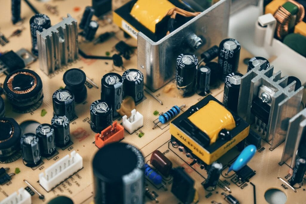
How to Identify Sections on the SMPS PCB
When you open a 5V adapter, the PCB may look confusing at first. But almost every board can be mentally divided into primary and secondary sides with clear functional sections.
6.1 Primary vs Secondary Side
The primary side is connected to 220V AC and usually has:
- Fuse, NTC, EMI components, bridge rectifier
- Big 400V capacitor, PWM IC, MOSFET, primary of transformer
The secondary side is the low-voltage area:
- Transformer secondary winding pins
- Fast diodes, output filter capacitors and inductor
- Feedback parts (TL431, optocoupler) and sometimes resistive divider
Often there is a visible isolation slot or gap milled in the board between primary and secondary.
6.2 Typical Visual Landmarks
- Biggest capacitor near mains input → high-voltage bulk capacitor.
- Yellow tape-wrapped transformer → center of the board.
- Small 4-pin device near transformer → often an optocoupler.
- Group of low-voltage capacitors near output wires/USB connector → output filter.
- Black IC near primary side → PWM controller or integrated switcher.
Common Problems in 220V to 5V SMPS (Symptoms)
Before jumping into measurements, observe how the adapter behaves. The basic symptoms help you narrow down which section to focus on.
| Symptom | Likely Area | Typical Causes |
|---|---|---|
| No output, LED off | Primary side | Blown fuse, shorted MOSFET, shorted bridge, open startup resistor, dead PWM IC |
| Output 0V, but fuse OK | Primary or feedback | Open startup resistor, bad high-voltage capacitor, bad optocoupler or TL431 |
| Output low (e.g., 3–4V instead of 5V) | Secondary/filter | Bad output capacitors, overloaded output, weak rectifier diode |
| Output fluctuating / clicking sound | Regulation/feedback | Bad feedback components, dried capacitors, overload causing hiccup mode |
| Adapter very hot | Primary or secondary load | Short or overload on output, wrong component values, poor ventilation |
| Noise in connected device | Secondary/filter | High ripple due to bad capacitors or missing filter inductor |
Step-by-Step SMPS Repair Procedure
Now let’s see a clear, repeatable process you can use to repair most 220V AC to 5V DC SMPS adapters. Follow the steps in order to avoid mistakes and time waste.
8.1 Step 1 – External Inspection
- Check the case for burn marks or melted plastic.
- Smell for strong burnt odor – indicates serious internal damage.
- Shake gently – loose pieces inside may indicate broken components.
8.2 Step 2 – Open the Case Safely
Many charger cases are ultrasonic-welded, not screwed. Use a thin flat screwdriver to carefully pry open along the seam. Work slowly to avoid cracking the board.
8.3 Step 3 – Visual Inspection of the PCB
- Look for burnt resistors, cracked ICs, blackened areas.
- Check for swollen or leaking capacitors on both primary and secondary sides.
- Look at solder joints – cold joints or cracks around heavy components (transformer, connectors).
8.4 Step 4 – Check Fuse and Short Circuits
- Test the fuse: Use multimeter in continuity mode. If open, do not replace blindly; there may be a serious short.
- Check for short between high-voltage rails: Measure resistance across the bulk capacitor. Very low resistance (near 0Ω) suggests a shorted MOSFET or bridge.
- Check bridge rectifier: If it is a 4-pin block, test using diode mode across each leg according to datasheet orientation. If four separate diodes, test each like a normal diode.
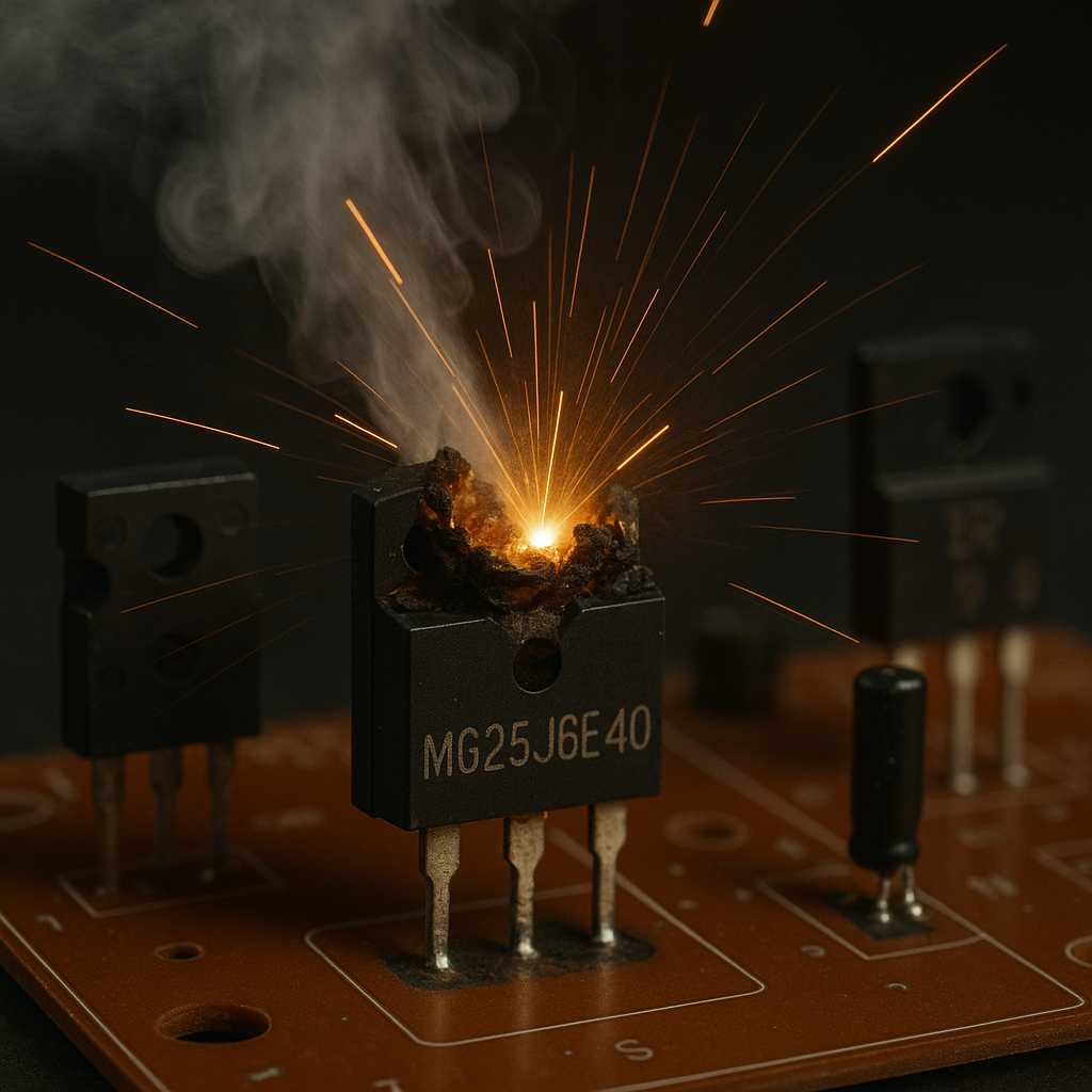
8.5 Step 5 – Check MOSFET / Switching Device
Remove power, discharge capacitors, and use resistance or diode mode to test MOSFET:
- Measure between Drain and Source – should not be a dead short.
- Gate to Source should show high resistance (no low short).
If MOSFET is shorted, it usually blows the fuse and can also damage the startup resistor, snubber, or PWM IC.
8.6 Step 6 – Check Startup Resistor and VCC Circuit
Find the high-value resistor(s) connecting from the high-voltage rail to the PWM IC’s VCC pin.
- Values often between 100kΩ and 1MΩ.
- Measure with the SMPS unplugged; if open or far from its color-code value, replace.
Also inspect small auxiliary diodes and capacitors around the PWM IC; a bad VCC capacitor can prevent startup or cause repeated restarting.
8.7 Step 7 – Check Secondary Side for Shorts
On the low-voltage side:
- Measure resistance across 5V output (without load). Very low resistance (<1Ω) may indicate a shorted output diode or IC on the load board (if still connected).
- Test the main secondary diode(s) in diode mode. If they read nearly 0 in both directions, they are short.
- Inspect output capacitors for bulging or leakage; test with ESR meter if available.
If the adapter is built into a larger device, disconnect the load and test SMPS alone to confirm whether the fault is inside the SMPS or in the device.
8.8 Step 8 – Check Feedback Circuit
If SMPS starts but output is unstable or incorrect, focus on:
- Optocoupler: Compare resistance between LED side and transistor side – should be isolated. Aging optocouplers may cause poor regulation.
- TL431 (or equivalent): Check surrounding resistors. Incorrect divider values can cause wrong output voltage.
- Small capacitors in feedback loop: Leaky caps here can cause oscillation, noise, or overshoot.
8.9 Step 9 – Power-Up with Series Lamp
After replacing obvious faulty parts (MOSFET, diode, fuse etc.), you can try a cautious power-up:
- Connect a series test lamp in line with the SMPS mains input.
- Power on and watch the lamp:
- If the lamp glows bright continuously → still a heavy short.
- If it flashes briefly and then dims → usually okay.
- Measure the 5V output with a multimeter (without load first).
8.10 Step 10 – Check Output Under Load
Once 5V is stable without load, connect:
- A known good 5V load (e.g., 5Ω 5W resistor for 1A, or a small USB load tester).
- Monitor voltage – it should remain near 5.0V and not drop below around 4.8V at rated current.
- Check temperature – warm is normal, but excessive heat indicates further issues.
Selecting and Replacing SMPS Components
After identifying bad components, you must select proper replacements. Using wrong ratings can lead to repeated failures or dangerous operation.
9.1 Fuse Selection
- Use the same fuse type (slow-blow or fast) and similar current rating.
- If fuse blows again immediately, don’t just up-rate the fuse; find the real cause of the short.
9.2 MOSFET / Integrated Switcher IC
For a discrete MOSFET:
- Voltage rating must be at least 600V for 220V mains applications.
- Current rating should match or exceed original.
- Use equal or lower RDS(on) if possible for efficiency.
For integrated switchers (TNY, VIPer etc.), try to get the exact part number. If not, use a close equivalent from the same family and follow manufacturer guidelines.
9.3 Diodes and Rectifiers
- Primary side rectifier: 1N4007 or bridge with 600–1000V rating.
- Secondary diodes: Use fast recovery or Schottky types with correct voltage and current rating (e.g., 40V/3A or more for 5V 2A adapter).
9.4 Capacitors (Electrolytic)
Always use capacitors with:
- Equal or higher voltage rating.
- Equal or slightly higher capacitance.
- 105°C temperature rating is preferred for SMPS.
- Low-ESR types on secondary side for better ripple performance.
9.5 Resistors and Startup Network
- Use resistors with similar value and wattage (often 1/4W–1W or more for startup resistor).
- Use flameproof types for critical positions (marked “FR” or “fusible”).
9.6 Optocoupler and TL431
- Common optocouplers like PC817 can be replaced by the same or equivalent part.
- TL431 is widely available; choose standard or high-precision variant based on original.
Testing, Reassembly, and Burn-In
Once the SMPS appears to work correctly, it is important to test it under realistic conditions before closing the case and handing it back to the customer.
10.1 No-Load Testing
- Check output voltage without any load.
- Ensure voltage is near 5.0V, not much higher (e.g., above 5.3V).
- Listen for unusual buzzing or ticking from transformer or board.
10.2 Load Testing
Connect a suitable load:
- For a 5V/1A adapter, use a 5Ω 5W resistor or a USB dummy load at 1A.
- Monitor voltage over 10–15 minutes.
- Check that it stays within an acceptable range (4.8–5.2V typically).
10.3 Thermal Check
- Touch components carefully (power off first) to gauge heat.
- MOSFET, transformer, and secondary diodes will be warm but should not be too hot to touch for a second or two.
- If extremely hot, re-check for overload, incorrect component values, or poor airflow.
10.4 Reassembly
- Ensure all solder joints are solid; no loose wires.
- Make sure the primary and secondary wires are well separated and insulated.
- Place insulating sheets back as originally found, especially under the PCB.
- Close the casing and secure it (screws or carefully applied glue).
Pro Tips to Reduce Noise, Heat, and Future Failures
Once you are comfortable repairing SMPS units, you can improve their reliability and performance using a few simple tricks.
11.1 Use High-Quality Capacitors
- Replace unknown or “no-name” capacitors with branded, low-ESR 105°C parts.
- Give a small boost to capacitance on the 5V output (e.g., from 470µF to 680µF) if space allows, to reduce ripple.
11.2 Improve Heat Dissipation
- Add a small heatsink to MOSFET or diodes if they run very hot (ensure no short to other components).
- Use thermal paste properly where metal tabs contact heatsinks.
11.3 Reduce Switching Noise
- Double-check snubber network values if replaced.
- Ensure proper grounding and cleaning of flux residues (excess flux can create leakage paths).
11.4 Avoid Overloading
- Advise users not to run a 1A adapter at 1A continuously; staying below 70–80% of rated current increases life.
- Use correct rating adapters for power-hungry USB devices.
FAQ – Frequently Asked Questions
Q1. Can I repair SMPS without an isolation transformer?
Technically yes, many technicians do it using only a series lamp. But for maximum safety, an isolation transformer is strongly recommended, especially for beginners. Never touch the primary side when power is on.
Q2. Why does the fuse keep blowing even after I replace it?
A repeatedly blowing fuse means there is still a short circuit or heavy overload in the SMPS. Check the MOSFET, bridge rectifier, secondary diode, and snubber network for shorts. Also verify output is not overloaded by the connected device.
Q3. My SMPS shows correct 5V without load but drops under load. Why?
Most commonly, this is due to weak output capacitors (high ESR) or a tired transformer/diode. Replace the secondary electrolytic capacitors with low-ESR types and check the output rectifier diode rating.
Q4. Is it safe if the output reads 5.3–5.4V?
Slightly high voltage at no load is often acceptable. But if it stays above 5.4V even under normal load, it may stress connected circuits. Check the feedback divider resistors and TL431; they might be out of tolerance.
Q5. How can I identify the PWM IC pinout?
Note the IC part number printed on the package and search for its datasheet (when you have internet access). Common pins are VCC, GND, Gate/Drain, Sense, and Feedback. Trace tracks on PCB to confirm – VCC usually comes from startup resistor and auxiliary winding; GND goes to primary negative rail.
Conclusion: 2025 SMPS Repair Can Be Easy with a Clear Method
Repairing a 220V AC to 5V DC SMPS power supply is not a mystery once you understand the block diagram, recognize the key components, and follow a systematic troubleshooting approach. Most faults fall into a few common categories – shorted MOSFET, blown fuse, bad capacitors, or issues in the startup and feedback circuits.
By following the step-by-step guide in this article, using a series test lamp, and respecting safety rules, you can confidently repair many chargers and adapters that would otherwise end up in the trash. Over time, your speed and success rate will improve, and you will start recognizing faults almost at a glance.
In upcoming guides, you can extend the same principles to 12V, 24V, and multi-output SMPS, as well as more advanced power supplies in TVs and desktop PCs. The core idea remains the same: understand the function of each block, measure correctly, and think step by step.
If you are building an electronics repair learning path or training center, you can use this 5V SMPS as one of the first power supply repair exercises for your students in 2025 and beyond.

Related more post’s :

Java Program Structure (Class, main, Methods)– Full Beginner Explanation
Java Program Structure (Class, main, Methods) – Beginner Guide | Tamil Technicians TT Tamil Technicians…

Install JDK + VS Code/IntelliJ Setup+ Your First Java Program (Windows)
Install JDK + VS Code/IntelliJ Setup + First Java Program (Windows) | Tamil Technicians TT…

JDK vs JRE vs JVM – Easy Explanation(Compile & Run Flow for Beginners)
JDK vs JRE vs JVM – Easy Explanation (Beginner Guide) | Tamil Technicians TT Tamil…

Java Introduction & Where Java is Used(Apps, Web, Banking, Android)
Java Introduction & Where Java is Used (Apps, Web, Banking, Android) | Tamil Technicians TT…

Next Step After C – What to Learn? (Embedded C, C++, Python, Linux Programming)
Next Step After C – What to Learn? (Embedded C, C++, Python, Linux Programming) |…
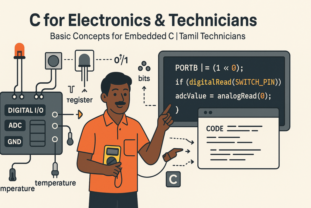
C for Electronics & Technicians – Basic Concepts for Embedded C
C for Electronics & Technicians – Basic Concepts for Embedded C | Tamil Technicians Tamil…
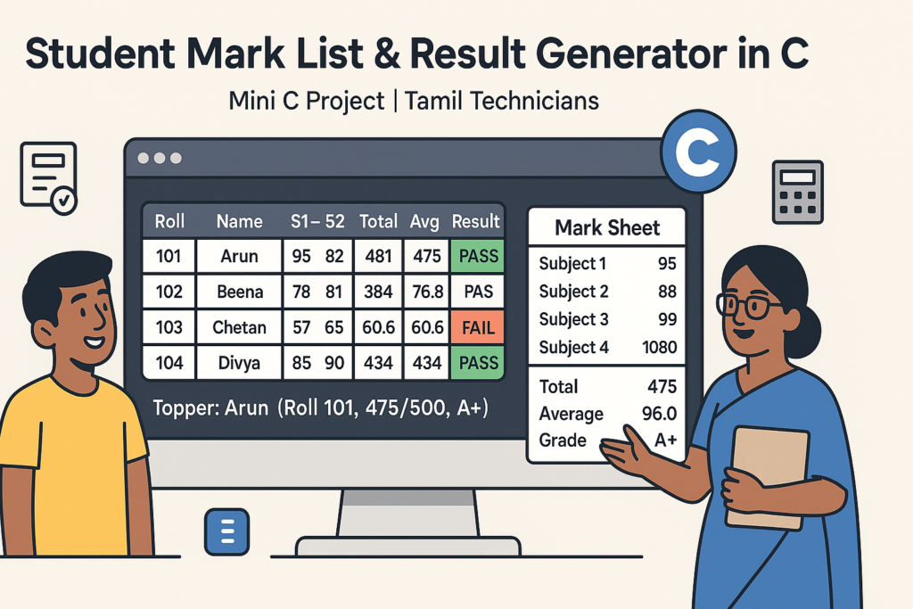
Mini C Project – Student Mark List & Result Generator in C (Console Project)
Mini C Project – Student Mark List & Result Generator in C (Console Project) |…
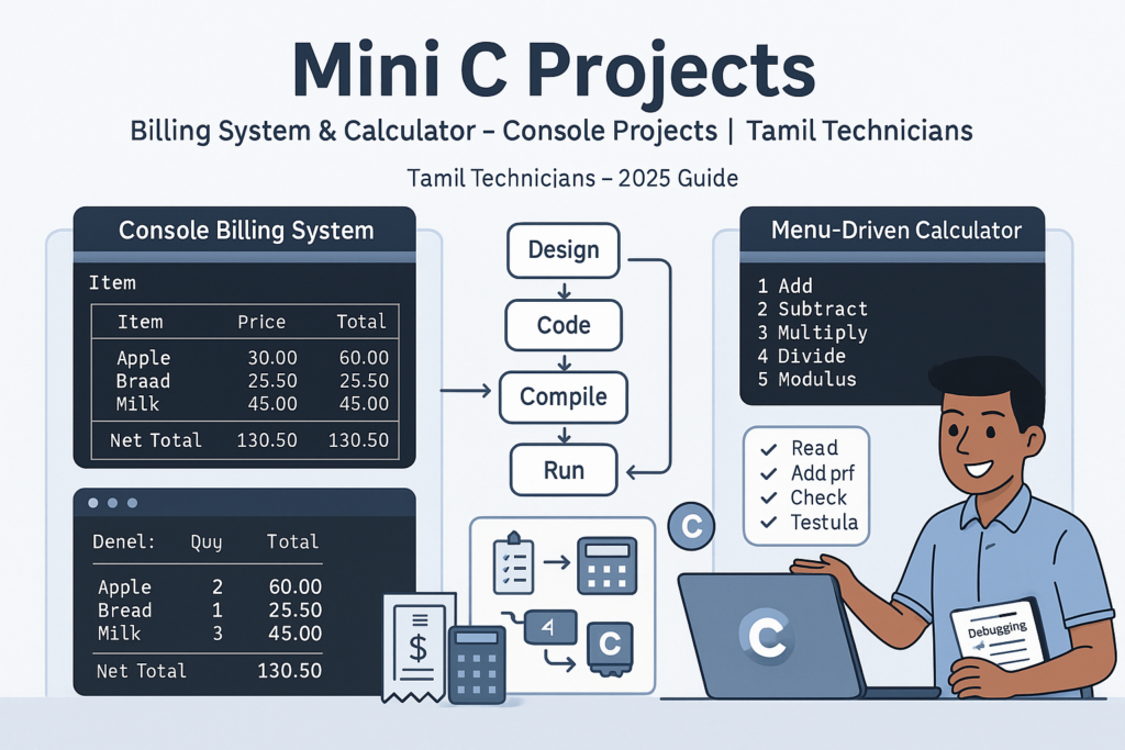
Mini C Projects – Simple Billing System & Calculator in C (Console Projects)
Mini C Projects – Simple Billing System & Calculator in C (Console Projects) | Tamil…
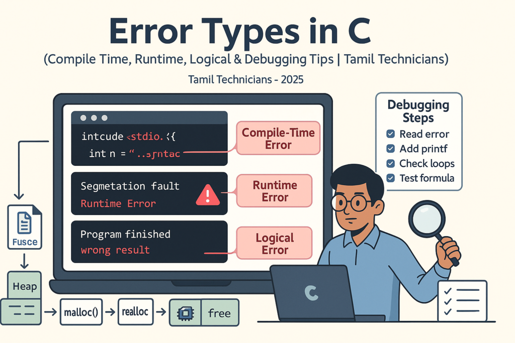
Error Types in C – Compile Time, Runtime, Logical Errors & Debugging Tips 2025
Error Types in C – Compile Time, Runtime, Logical Errors & Debugging Tips | Tamil…
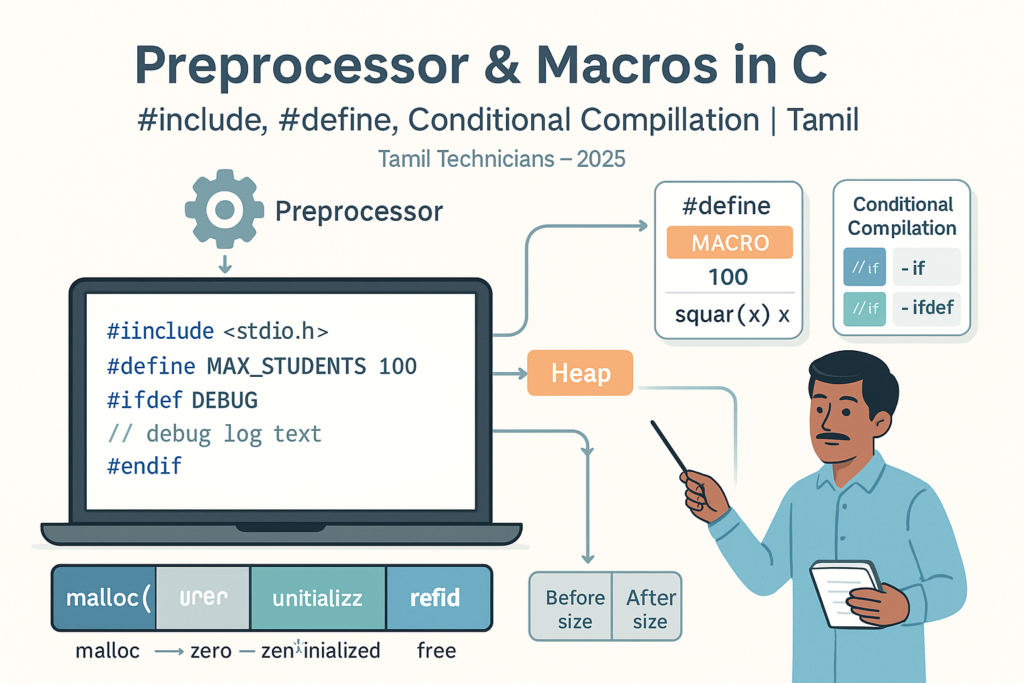
Preprocessor & Macros in C – #include, #define, Conditional Compilation
Preprocessor & Macros in C – #include, #define, Conditional Compilation | Tamil Technicians Tamil Technicians…

Dynamic Memory Allocation – malloc(), calloc(), realloc(), free() Basics
Dynamic Memory Allocation in C – malloc(), calloc(), realloc(), free() Basics | Tamil Technicians Tamil…
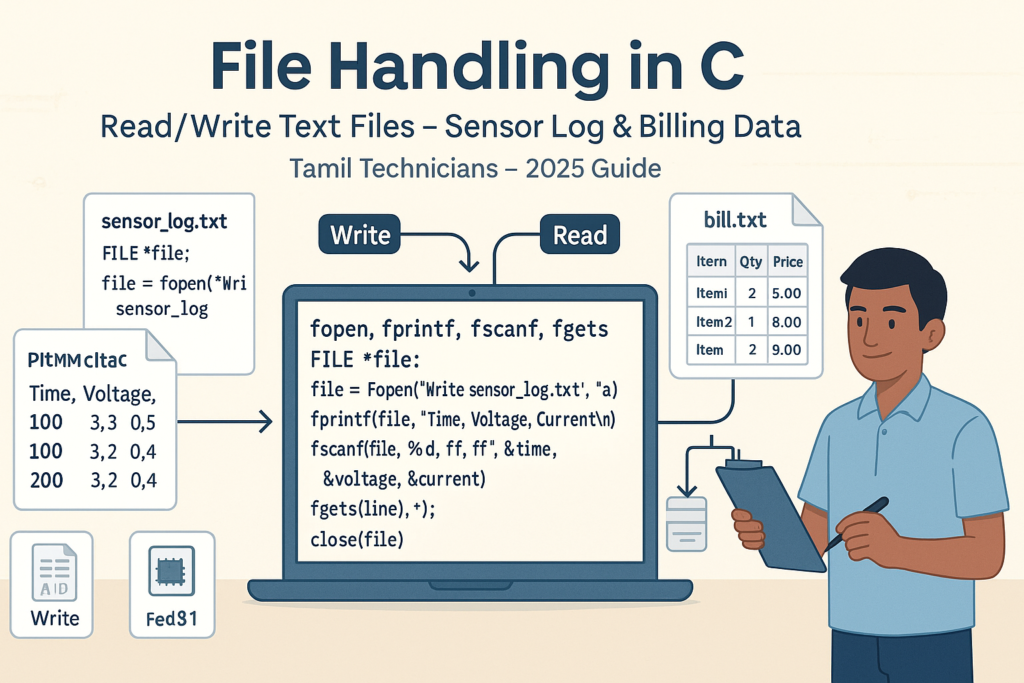
File Handling in C – Read/Write Text Files (Sensor Log, Billing Data Examples) 2025
File Handling in C – Read/Write Text Files (Sensor Log, Billing Data Examples) | Tamil…
How to Repair 220V AC to 5V DC SMPS Power Supply Easily – Complete 2025 Guide
How to Repair 220V AC to 5V DC SMPS Power Supply Easily – Complete 2025…
How to Assemble a 5.1 Amplifier Easily – Complete 2025 Guide
How to Assemble a 5.1 Amplifier Easily (2025 Full Guide) | Tamil Technicians English How…
Top 10 Secrets in CRT TV Service in 2025
Top 10 Secrets in CRT TV Service in 2025 (Professional Technician Guide) CRT TV Service…

Storage Classes in C – auto, static, extern, register (Lifetime & Scope)
Storage Classes in C – auto, static, extern, register (Lifetime & Scope) | Tamil Technicians…

Structures in C – Struct with Examples (Student, Product, Device Data)
Structures in C – Struct with Examples (Student, Product, Device Data) | Tamil Technicians Tamil…
Pointers with Arrays, Strings & Functions – Real Use Cases
Pointers with Arrays, Strings & Functions – Real Use Cases | Tamil Technicians Tamil Technicians…
Pointers in C – Step-by-Step Visual Explanation for Beginners
Pointers in C – Step-by-Step Visual Explanation for Beginners | Tamil Technicians Tamil Technicians –…
Call by Value vs Call by Reference – Simple Pointer Examples in Tamil
Call by Value vs Call by Reference – Simple Pointer Examples in Tamil | Tamil…
Functions in C – User Defined Functions, Arguments, Return Types
Functions in C – User Defined Functions, Arguments, Return Types | Tamil Technicians Tamil Technicians…

Unions & Enums in C – Where and Why to Use Them?
Unions & Enums in C – Where and Why to Use Them? | Tamil Technicians…
Strings in C – char Array, gets(), puts(), String Functions (strlen, strcpy, etc.)
Strings in C – char Array, gets(), puts(), String Functions (strlen, strcpy, etc.) | Tamil…
2D Arrays in C – Tables, Matrices & Small Mini-Projects
2D Arrays in C – Tables, Matrices & Small Mini-Projects | Tamil Technicians Tamil Technicians…
Arrays in C – 1D Array Basics with Practical Examples (Marks, Bills, Readings)
Arrays in C – 1D Array Basics with Practical Examples (Marks, Bills, Readings) | Tamil…
Break, Continue & goto in C – When to Use and When to Avoid?
Break, Continue & goto in C – When to Use and When to Avoid? |…

Loops in C – for, while, do-while Complete Guide (Patterns & Practice)
Loops in C – for, while, do-while Complete Guide (Patterns & Practice) | Tamil Technicians…

switch–case in C – Menu Programs & Real Life Examples for Technicians
switch–case in C – Menu Programs & Real Life Examples for Technicians | Tamil Technicians…
Control Statements in C – if, if-else, nested if, else-if ladder (Tamil Explanation)
Control Statements in C – if, if-else, nested if, else-if ladder (Tamil Explanation) | Tamil…

Operators in C – Arithmetic, Relational, Logical & Assignment (with Examples)
Operators in C – Arithmetic, Relational, Logical & Assignment (with Examples) | Tamil Technicians Tamil…
Input & Output in C – printf(), scanf() Step-by-Step Guide 2025
Input & Output in C – printf(), scanf() Step-by-Step Guide | Tamil Technicians Tamil Technicians…

C Variables, Data Types & Constants Explained in Simple Tamil
C Variables, Data Types & Constants Explained in Simple Tamil | Tamil Technicians Tamil Technicians…

Structure of a C Program – main(), Header Files & How Code Runs?
Structure of a C Program – main(), Header Files & How Code Runs? | Tamil…

What is Programming & Why C is Important? (C Programming in Tamil for Beginners) | Tamil Technicians
What is Programming & Why C is Important? (C Programming in Tamil for Beginners) |…

C Language Introduction & Setup Guide for Beginners 2025
C Language Course Introduction & Setup Guide (Windows, Linux, macOS) | Tamil Technicians Tamil Technicians…
Ultimate Guide to Power Supply for Electronics Repair & Projects
Ultimate Guide to Power Supply for Electronics Repair & Projects | Tamil Technicians Ultimate Guide…

Online Electronics Repair Training in Tamil | TAMIL TECHNICIANS
Online Electronics Repair Training in Tamil | [TAMIL TECHNICIANS] Online Electronics Repair Training in Tamil…
iPhone 17 Series – Complete Guide (Features, Price in India, Specs)
iPhone 17 Series – Complete Guide (Features, Price in India, Specs) | Tamil Technicians Home…
iPhone 17 Series – முழுமையான வழிகாட்டி (Features, Price in India, Specs)
iPhone 17 Series – முழுமையான வழிகாட்டி (Features, Price in India, Specs) | Tamil Technicians Home…
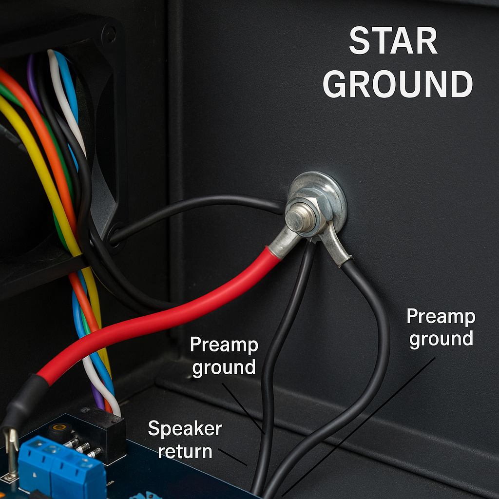
Kill Audio Hum: A Practical Guide to Star Ground & Chassis Ground
Kill Audio Hum: A Practical Guide to Star Ground & Chassis Ground TamilTechnicians • Audio…

Edge AI: Cloud இல்லாமல் Mobile & IoT Devices‑ல் Real‑Time Intelligence (2025)
Edge AI: Cloud இல்லாமல் Mobile & IoT Devices‑ல் Real‑Time Intelligence Edge AI 2025 Guide Edge…

Offline AI Models: Mobile Apps-க்கு வேகமும் Privacy‑யும் தரும் அடுத்த Revolution
Offline AI Models: Mobile Apps-க்கு வேகமும் Privacy‑யும் தரும் அடுத்த Revolution AI • Mobile Development Offline…
🔥 Induction Stove Heat ஆகவில்லையா? இந்த 5 Faults வீடிலேயே Fix பண்ணலாம்!
🔥 Induction Stove Not Heating? Tamil Repair Guide 🔥 Induction Stove Heat ஆகவில்லையா? இந்த 5…

Smartphone Dead Issue? Full Board-Level Repair Steps
Smartphone Dead Issue? Full Board-Level Repair Steps 📱 Smartphone Dead Issue? Full Board-Level Repair Steps…
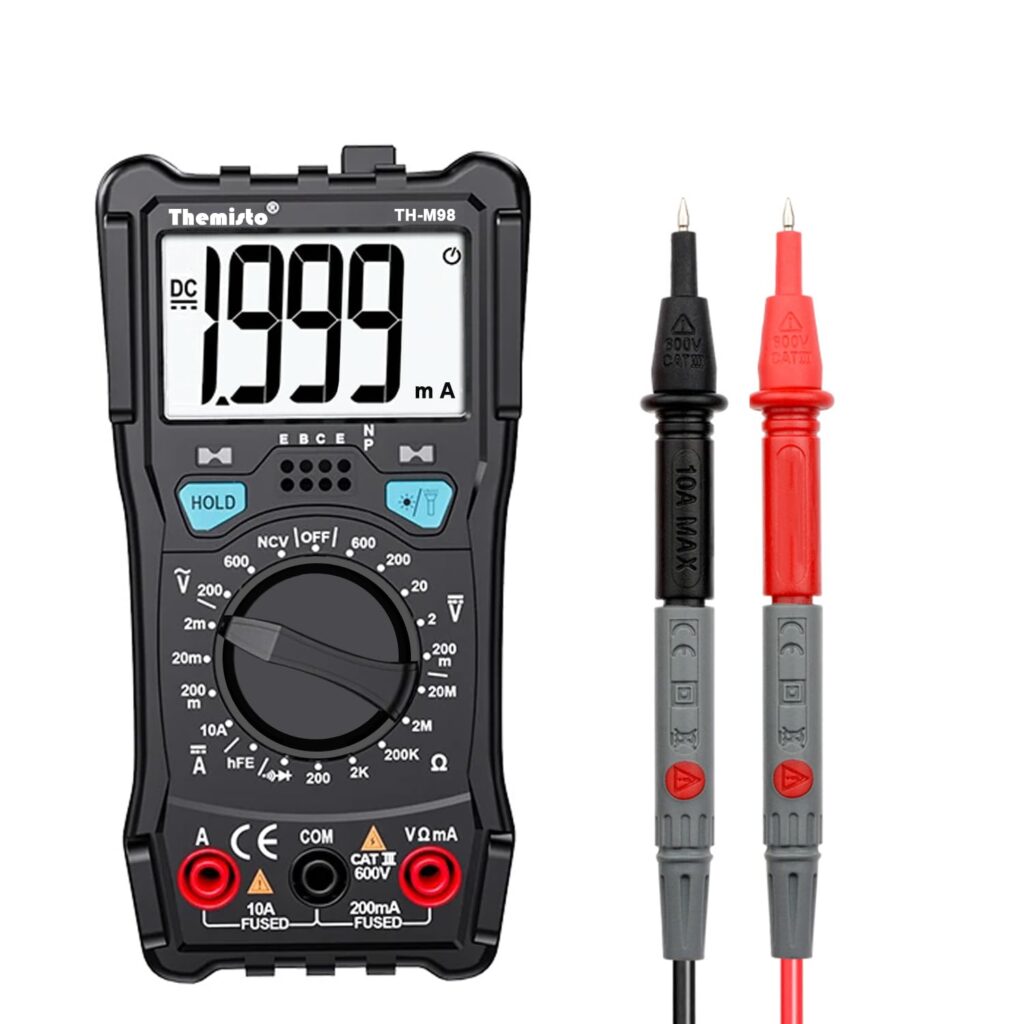
Top 5 Multimeters Under ₹1000 for Beginners in India (2025) – Expert Guide
Top 5 Multimeters Under ₹1000 for Beginners (2025 Guide) Top 5 Multimeters Under ₹1000 (2025…
Introduction to Induction Stove Technology Easy Guide – 2025
Introduction to Induction Stove Technology 🔌 Introduction to Induction Stove Technology What is an Induction…

சிப்-லெவல் மொபைல் பழுதுபார்க்கும் படிப்பு – முழு வழிகாட்டி
சிப்-லெவல் மொபைல் பழுதுபார்க்கும் படிப்பு 🔧சிப்-லெவல் மொபைல் பழுதுபார்ப்பு என்றால் என்ன? சிப்-லெவல் மொபைல் பழுதுபார்ப்பு என்பது மொபைல் ஃபோனின்…
Chip-Level Mobile Repair Course – Full Guide
🔧 What is Chip-Level Mobile Repair? Chip-level mobile repair refers to the process of diagnosing…
🛠️ Top Mobile Repair Issues Trending in 2025 – And How to Fix Them
🛠️ Top 5 Mobile Repair Issues in 2025 and How to Fix Them Like a…

Top 10 Must-Have Mobile Repair Tools for Starters quick [2025 Guide]
Top 10 Must-Have Mobile Repair Tools for Starters [2025 Guide] 🛠️ Top 10 Must-Have Mobile…
r